CO₂ Absorption Using MEA in Aspen Plus
CO₂ Absorption Using MEA in Aspen Plus: A Practical Simulation Insight
Introduction
With the growing global focus on decarbonization and sustainability, carbon capture has emerged as a key technology to mitigate CO₂ emissions from industrial sources. Among the available techniques, chemical absorption using Monoethanolamine (MEA) remains the most commercially proven and widely implemented for post-combustion CO₂ capture.
In this blog, we explore how CO₂ absorption using MEA can be modeled and analyzed using Aspen Plus — a leading process simulation software. Such simulations are invaluable for understanding process performance, optimizing operating parameters, and minimizing energy consumption in carbon capture systems.
1. Process Overview
The MEA-based CO₂ absorption system consists of two main sections:
Absorber (Packed Column):
- Flue gas containing CO₂ flows upward and contacts a downward-flowing aqueous MEA solution.
- CO₂ chemically reacts with MEA to form carbamate and bicarbonate compounds.
- The cleaned gas exits from the top of the absorber, while the CO₂-rich solution leaves from the bottom.
Stripper (Regenerator):
- The CO₂-rich MEA solution is preheated and fed to the regenerator column.
- Heat (usually from steam) drives the reverse reaction, releasing CO₂ and regenerating MEA.
- The lean MEA is recycled back to the absorber for continuous operation.
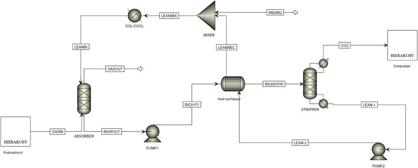
Schematic representation of the absorber and stripper sections in an MEA-based carbon capture system.
2. Simulation Setup in Aspen Plus
Step 1: Property Method Selection
Use the ELECNRTL (Electrolyte NRTL) property method to handle electrolyte equilibria, ionic interactions, and chemical reactions in the CO₂–MEA–H₂O system.
Step 2: Component Definition
Define both conventional and ionic species using Aspen’s Electrolyte Wizard:
- Conventional: CO₂, H₂O, MEA
- Ionic: MEACOO⁻, MEAH⁺, H⁺, HCO₃⁻, CO₃²⁻
Step 3: Reaction Setup
Include the following equilibrium reactions in the liquid phase:
- CO₂ + 2MEA ⇌ MEACOO⁻ + MEAH⁺
- CO₂ + H₂O ⇌ H⁺ + HCO₃⁻
- HCO₃⁻ ⇌ H⁺ + CO₃²⁻
Reaction constants are available in literature or can be input manually.
Step 4: Process Flowsheet
A typical Aspen Plus flowsheet includes:
- Absorber (RadFrac / Rate-based column)
- Stripper (RadFrac with reboiler & condenser)
- Lean/Rich Heat Exchanger
- Pumps & Flash Drums for circulation and pressure control
3. Typical Operating Conditions
| Parameter | Absorber | Stripper |
|---|---|---|
| Pressure | 1.1 bar | 1.8 bar |
| Temperature | 40–60°C | 100–120°C |
| MEA Concentration | 20–30 wt% | — |
| CO₂ Loading | 0.2–0.4 (lean) → 0.5–0.6 (rich) | — |
These values are tuned based on flue gas composition and desired CO₂ capture efficiency.
4. Simulation Insights
Once simulated, Aspen Plus provides detailed information such as:
- CO₂ capture efficiency: 85–95% achievable
- Energy requirement: ~3.5–4.0 GJ/ton CO₂ (reboiler duty)
- Lean/Rich loading impact: Affects regeneration energy and solvent circulation rate
- Column profiles: Temperature and composition trends identify reaction and heat zones
5. Engineering Takeaways
- MEA concentration optimization is critical — higher concentrations improve absorption but increase regeneration energy.
- Rate-based modeling offers better insight into mass transfer and reaction kinetics than simple equilibrium methods.
- Energy integration (lean/rich heat exchange) can significantly reduce overall utility demand.
- Integration with Aspen Energy Analyzer or Aspen HYSYS Dynamics enhances process optimization and control design.
6. Conclusion
Simulating CO₂ absorption using MEA in Aspen Plus enables engineers to design efficient and cost-effective carbon capture systems, analyze performance under varying conditions, and optimize energy use and solvent loading. This supports the transition toward net-zero operations in refineries, petrochemical plants, and power industries.
Aspen Plus provides a virtual platform to explore and refine CO₂ capture processes before actual implementation — saving time, cost, and resources.